
Solar Tracking and Custom Electronics ProductsShipping charges will be based on shipping selection for the first item in your cart.
Heliotrack Dual Axis Tracking Controller V3.3Downloadable PDF (Current V3.3 controllers)
Features: Applications: Specifications:
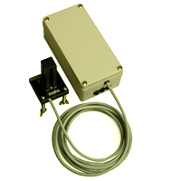
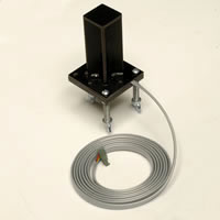
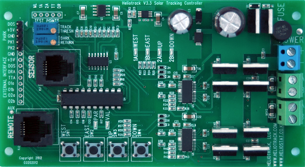
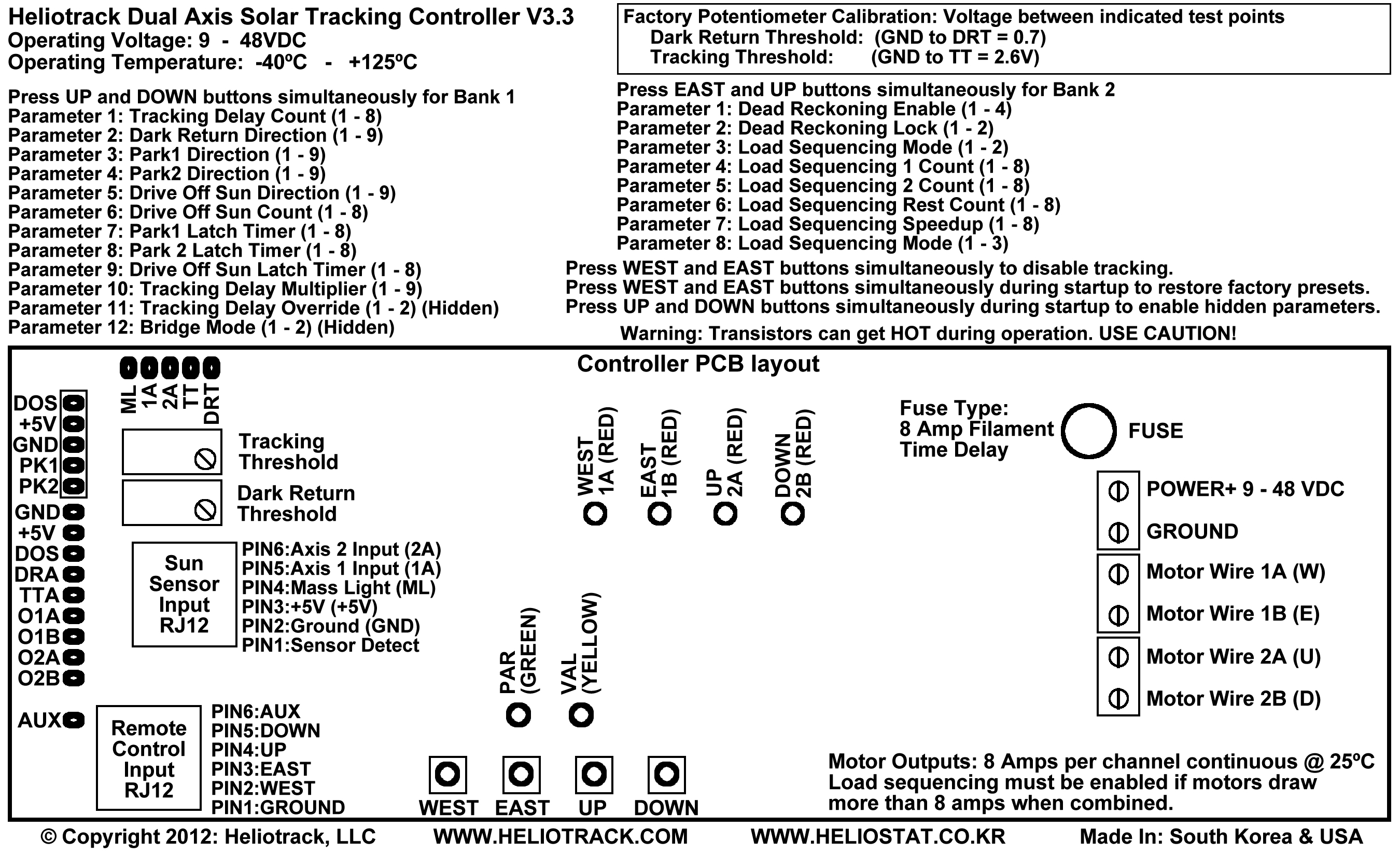
Controller circuit description: Although this controller was designed primarily for dual axis solar tracking it can also be used for control of other loads requiring DC current up to 4 amps. Possible applications include, but are not limited to, circulation pumps, relays, solenoids, fans, motion control, and system monitoring. • Power: 9-48 VDC (volts direct current) *** Never apply power directly to the motor terminals , this will destroy the driver transistors and incur a $75 fix it fee. YOU MUST disconnect the motor wires from the tracking controller if you want to test your motors by connecting them directly to the power supply. If you do damage the boards from mishandling then remove the controller board from the plastic enclosure and send it back to us in a padded mailer. We will fix the board within one week and ship it back to you USPS Priority. LED indicators: Installation instructions: 2) Connect the motor wires from your actuators to the motor terminals on the circuit board. 3) The sun sensor should be mounted to the tracking plane (solar panels or concentrator) with the cable leading in the Tilt-Down direction, or South when the tracker is at the Noon position in the Northern Hemisphere. The sensor comes with floating spring mounts for convenient calibration. Remove the wing nuts and one washer from each mounting bolt (this leaves one washer and the spring on each bolt). Pass the three bolts through pre-drilled holes on your sensor bracket, then replace the washer and then the wing nut on each bolt. This provides a spring-loaded tripod mount for your sensor. Fine-tune the alignment of the sensor by turning the wing nuts in the appropriate direction. 4) WITHOUT THE POWER ON... connect your 9 - 48 VDC power supply wires to the power terminals on the tracking circuit. Be sure to verify polarity, especially when bypassing the reverse protection diode for high-amperage operation. Verify connections and turn on the power. The GREEN LED should flash quickly 15 times while the controller loads the user saved parameters from memory. 5) If an actuator is tracking in the wrong direction, disconnect the power, reverse the polarity of the motor wires for that actuator, and reconnect the power. 6) Replace the cover on the control box when you are satisfied that everything is working properly. Make sure that the stress grommet on the sun sensor cable is seated in the notch on the controller box. For permanent outdoor installations it is a good idea to put a bead of caulking around the lid of the box before replacing it to prevent moisture from getting in. Load Sequencing (Duty Cycle): Load sequencing can also reduce the on-time of each actuator to prevent overheating of the driver transistors when using actuators drawing greater than 8 amps. Using Load Sequencing in this way also requires replacing the stock filament fuses with polyfuses that can permit greater amperage spikes without tripping. Tracking Delay: Short Circuit Protection: Relay Controller Option: Limit Switches: Disclaimer: Startup Button Functions Pressing WEST button & EAST button while powering up the controller restores the factory presets. Pressing UP button & DOWN button while powering up the controller enables hidden Parameters 11 (Time Delay Override) and 12 (Bridge Mode) in the programming mode. Operation Button Functions Remote Control Pressing EAST button will turn on motor wire 1B (E) Pressing UP button will turn on motor wire 2A (U) Pressing DOWN button will turn on motor wire 2B (D) Pressing WEST and EAST buttons simultaneously will toggle between Tracking Enable and Tracking Disable. Entering or exiting this mode is indicated by three short blinks. When tracking is disabled the green and yellow lights will continue to blink three short blinks. Pressing Button 3&4 simultaneously enters the programming mode.
Programming Mode (V3.3 controller with V3.1 firmware) VAL LED (Green) 1 indicates which parameter is selected. WEST button: EAST button: UP button: Down button:
Programmable Parameters Bank 1
*SPECIAL ACCESS PARAMETERS: Press Button 3&4 during startup to enable access to these parameters in Programming Mode. Tracking Delay Override: Disabling the Tracking Delay may cause damage to the motor driver transistors. Overriding the Tracking Delay enables high frequency output and should not to be used with the stock H-Bridge driver in this controller. Bridge Mode: Proper bridge wiring must be observed when Bridge Mode is enabled or the fuses will blow and the driver transistors may be damaged.
Bank 1 Parameter 1: Tracking Delay Count
|
||||||||||||||||||||||||||||||||||||||||||||||||||||||||||||||||||||||||||||||||||||||||||||||||||||||||||||||||||||||||||||||||||||||||||||||||||||||||||||||||||||||||||||||||||||||||||||||||||||||||||||||||||||||||||||||||||||||||||||||||||||||||||||||||||||||||||||||||||||||||||||||||||||||||||||||||||||||||||||||||||||||||||||||||||||||||||||||||||||||||||||||||||||||||||||||||||||||||||||||||||||||||||||||||||||||||||||||||||||||||||||||||||||||||||||||||||||||||||||||||||||||||||||||||||||||||||||||||
| YELLOW LED Blinks |
Tracking Delay count: Rest time between tracking corrections. Actual time depends on Tracking Delay Multiplier. Tracking Delay is applied to Dark return, Tracking Threshold, and On-Sun signals. |
|
|
Tracking Delay Count |
* Tracking Delay Time |
1 |
1 |
1.8 seconds |
2 |
3 |
6 seconds |
3 |
7 |
14 seconds |
4 |
15 (Factory Default) |
31 seconds (Factory Default) |
5 |
31 |
64 seconds |
6 |
63 |
133 seconds |
7 |
127 |
266 seconds |
8 |
255 |
532 seconds |
* Tracking Delay Times in this table are only valid when the Tracking Delay Multiplier (Bank 2 Parameter 10) value is set to the factory default of 4.
The Tracking Delay Count sets the amount of time the controller waits between tracking corrections.
The sun traverses the sky at a rate of 1 degree every four minutes; so a Tracking Delay Time of four minutes would limit the tracking accuracy to 1 degree. The default Tracking Delay Time of 31 seconds represents an accuracy of about 1/8 degree. Change the Tracking Delay Multiplier (Parameter 11) to achieve Tracking Delays that are greater or less than the Tracking Delays available in this table.
Bank 1 Parameter 2: Dark Return Direction
Green LED: 2 Blinks
Yellow LED: 1 – 9 Blinks
Default Value = 1
| YELLOW LED Blinks |
Dark Return Direction: Activated when the sun sensor’s Mass Light output (Pin: ML) is less than the Dark Return Threshold (Pin: DRT) which is set by the Dark Return Threshold potentiometer (R35) |
1 |
Motor 1 off / Motor 2 off (Factory default) |
2 |
Motor 1 East / Motor 2 off |
3 |
Motor 1 West / Motor 2 off |
4 |
Motor 1 off / Motor 2 Down |
5 |
Motor 1 East / Motor 2 Down |
6 |
Motor 1 West / Motor 2 Down |
7 |
Motor 1 off / Motor 2 Up |
8 |
Motor 1 East / Motor 2 Up |
9 |
Motor 1 West / Motor 2 Up |
NOTE: East and West directions are reversed in the Southern Hemisphere when the Tracker is facing North.
The Dark Return Direction is the direction the tracker will move when the Mass Light output voltage of the Sun Sensor (Test Point ML) is less than the voltage set by the Dark Return Threshold potentiometer (Test Point DRT). The Dark Return output will be on the entire night so limit switches are required on the actuators to stop the tracker in the sunrise position (East Limit).
The most common value for the Dark Return Direction parameter in the Northern Hemisphere is 2; in the Southern Hemisphere it is 3.
Bank 1 Parameter 3: Park 1 Direction
Green LED: 3 Blinks
Yellow LED: 1 – 9 Blinks
Default Value = 1
| YELLOW LED Blinks |
Park 1 Direction: Activated when the Park 1 (Pin: PK1) is connected to Ground. Park 1 supersedes Park 2, Drive Off Sun, and Dark Return. Most likely used for stowing the tracker at the horizontal (tilt up) limit for high wind or the vertical (tilt down) limit for Hail. |
1 |
Motor 1 off / Motor 2 off (Factory default) |
2 |
Motor 1 East / Motor 2 off |
3 |
Motor 1 West / Motor 2 off |
4 |
Motor 1 off / Motor 2 Down |
5 |
Motor 1 East / Motor 2 Down |
6 |
Motor 1 West / Motor 2 Down |
7 |
Motor 1 off / Motor 2 Up |
8 |
Motor 1 East / Motor 2 Up |
9 |
Motor 1 West / Motor 2 Up |
NOTE: East and West directions are reversed in the Southern Hemisphere (Tracker facing North).
The tracker will turn on the motor(s) in the Park 1 direction whenever the Park 1 pin (PK1) is connected to ground. This function can be used to park the tracker during adverse weather conditions like high wind or hail. The motor wires will be the entire time the Park 1 pin is connected to ground requiring limit switches to keep the actuators from over-traveling.
Park 1 has priority over Park 2, Drive Off Sun, and Dark Return.
Bank 1 Parameter 4: Park 2 Direction
Green LED: 4 Blinks
Yellow LED: 1 – 9 Blinks
Default Value = 1
| YELLOW LED Blinks |
Park 2 Direction: Activated when the Park 2 (Pin: PK2) is switched to Ground. Park 2 supersedes Drive Off Sun, and Dark Return. Parking for weather or a system fault. |
1 |
Motor 1 off / Motor 2 off (Factory default) |
2 |
Motor 1 East / Motor 2 off |
3 |
Motor 1 West / Motor 2 off |
4 |
Motor 1 off / Motor 2 Down |
5 |
Motor 1 East / Motor 2 Down |
6 |
Motor 1 West / Motor 2 Down |
7 |
Motor 1 off / Motor 2 Up |
8 |
Motor 1 East / Motor 2 Up |
9 |
Motor 1 West / Motor 2 Up |
NOTE: East and West directions are reversed in the Southern Hemisphere (Tracker facing North)
The tracker will turn on the motor(s) in the Park 2 direction whenever the Park 2 pin (PK2) is connected to ground. This function can be used to park the tracker during adverse weather conditions like high wind or hail. The motor wires will be the entire time the Park 2 pin is connected to ground requiring limit switches to keep the actuators from over-traveling.
Park 2 has priority over Drive Off Sun, and Dark Return.
Bank 1 Parameter 5: Drive Off Sun Direction
Green LED: 5 Blinks
Yellow LED: 1 – 9 Blinks
Default Value = 1
| YELLOW LED Blinks |
Drive Off Sun Direction: Activated when the Drive Off Sun (Pin: DOS) is grounded (GROUND or Pin: GND) |
1 |
Motor 1 off / Motor 2 off (Factory default) |
2 |
Motor 1 East / Motor 2 off |
3 |
Motor 1 West / Motor 2 off |
4 |
Motor 1 off / Motor 2 Down |
5 |
Motor 1 East / Motor 2 Down |
6 |
Motor 1 West / Motor 2 Down |
7 |
Motor 1 off / Motor 2 Up |
8 |
Motor 1 East / Motor 2 Up |
9 |
Motor 1 West / Motor 2 Up |
NOTE: East and West directions are reversed in the Southern Hemisphere (Tracker facing North)
When the Drive Off Sun pin (DOS) is connected to ground the tracker will move in the Drive Off Sun Direction for the time specified by the Drive Off Sun Count and then stop. When the DOS pin is released from ground the DOS counter will reset.
This function is designed to move the tracker off sun when the solar collector is overheating. This is important in Concentrated Solar Power (CSP) applications where the collector may be damaged if recirculation of the working fluid is interrupted, or when overheating can cause the working fluid to boil causing critical buildup of system pressure.
Bank 1 Parameter 6: Drive Off Sun Count
Green LED: 6 Blinks
Yellow LED: 1 – 8 Blinks
Default Value = 4
| YELLOW LED Blinks |
Drive Off Sun Count: Time that the tracker moves in the Drive Off Sun direction while the DOS pin is grounded. When the count expires the tracker will rest until The DOS pin is released from ground. Park 1 and Park 2 will override the DOS function. Actual time depends on Tracking Delay Multiplier. |
1 |
0.5 Seconds |
2 |
1.7 Seconds |
3 |
3.5 Seconds |
4 |
8 Seconds (Factory default) |
5 |
16 Seconds |
6 |
32 Seconds |
7 |
64 Seconds |
8 |
128 Seconds |
Drive Off Sun Count is the amount of time that the tracker will move in the Drive Off Sun Direction when the DOS pin is connected to ground. The Drive Off Sun Count is reset whenever the DOS pin is released from ground.
Bank 1 Parameter 7: Park 1 Latch Timer
Green LED: 7 Blinks
Yellow LED: 1 – 8 Blinks
Default Value = 1
| YELLOW LED Blinks |
Park 1 Latch Timer: This is the time that the controller will wait to resume Tracking, Dead Reckoning, or Dark Returning after Park 1 has been released. |
1 |
OFF (Factory default) |
2 |
30 Seconds |
3 |
60 Seconds |
4 |
120 Seconds |
5 |
240 Seconds |
6 |
480 Seconds |
7 |
960 Seconds |
8 |
1920 Seconds |
Park Latch Timers are used to delay the resumption of tracking operations after the respective park pin has been released. For example, if Park 1 is being triggered by a high wind alarm then the Park 1 Latch Timer will allow the user to set how long the wind needs to be below a certain speed before tracking will resume. The Park 1 Latch Timer will be cleared if either Park 2 or DOS are activated.
Bank 1 Parameter 8: Park 2 Latch Timer
Green LED: 8 Blinks
Yellow LED: 1 – 8 Blinks
Default Value = 1
| YELLOW LED Blinks |
Park 2 Latch Timer: This is the time that the controller will wait to resume Tracking, dead reckoning, or Dark Returning after Park 2 has been released. |
1 |
OFF (Factory default) |
2 |
30 Seconds |
3 |
60 Seconds |
4 |
120 Seconds |
5 |
240 Seconds |
6 |
480 Seconds |
7 |
960 Seconds |
8 |
1920 Seconds |
Park Latch Timers are used to delay the resumption of tracking operations after the respective park pin has been released. For example, if Park 2 is being triggered by a hail alarm then the Park 2 Latch Timer will allow the user to set how long the hail storm needs to have passed before tracking will resume. The Park 2 Latch Timer will be cleared if either Park 1 or DOS are activated.
Bank 1 Parameter 9: DOS Latch Timer
Green LED: 6 Blinks
Yellow LED: 1 – 8 Blinks
Default Value = 4
| YELLOW LED Blinks |
DOS 1 Latch Timer: This is the time that the controller will wait to resume Tracking, dead reckoning, or Dark Returning after DOS has been released. |
1 |
OFF (Factory default) |
2 |
30 Seconds |
3 |
60 Seconds |
4 |
120 Seconds |
5 |
240 Seconds |
6 |
480 Seconds |
7 |
960 Seconds |
8 |
1920 Seconds |
Park Latch Timers are used to delay the resumption of tracking operations after the respective park pin has been released. For example, if DOS is being triggered by a collector overheat alarm then the DOS Latch Timer will allow the user to set how long the overheat condition needs to be corrected before tracking will resume. The DOS Latch Timer will be cleared if either Park 1 or Park 2 are activated.
Bank 1 Parameter 10: Tracking Delay Multiplier
Green LED: 10 Blinks
Yellow LED: 1 – 9 Blinks
Default Value = 4
| YELLOW LED Blinks |
Drive Off Sun Direction |
1 |
X 1 |
2 |
X 2 |
3 |
X 3 |
4 |
X 4 (Factory default) |
5 |
X 5 |
6 |
X 6 |
7 |
X 7 |
8 |
X 8 |
9 |
X 9 |
Tracking Delay Multiplier is used to extend or reduce the factory default Tracking Delay Times. The minimum Tracking Delay Time is approximately .25 seconds when using a multiplier of 1. This setting is used for extremely precise tracking.
The maximum Tracking Delay Time is about 20 minutes when using a multiplier of 9. This setting is good for PV tracking where having fewer tracking movements per day may be preferable to high accuracy.
See the Tracking Delay Time Table to determine possible Tracking Delay Time possibilities.
Bank 1 Parameter 11: Tracking Delay Override (*Hidden Parameter)
Green LED: 11 Blinks
Yellow LED: 1 – 2 Blinks
Default Value = 1
| YELLOW LED Blinks |
Time Delay Override: Disables Time Delay between tracking corrections. Caution!! this may cause high frequency oscillations that can destroy the transistors if the controller has the stock H-Bridge output. |
1 |
Tracking Delay Enabled (Factory default) |
2 |
Tracking Delay Disabled |
Tracking Delay Override disables the Tracking Delay Timer causing the controller motor outputs to react instantaneously to signals from the sun sensor. This parameter should be never be enabled when using the stock controller driver transistors because the high speed switching frequencies can damage the transistors.
This parameter enables high speed control of an external driver circuit and requires that the controller PCB be modified as a logic controller; this is done by removing the four N-MOSFET driver transistors or all of the driver transistors depending on the application.
Please contact us for more information if you plan on enabling this parameter or the warranty may be void.
Bank 1 Parameter 12: Motor Bridging Mode (*Hidden Parameter)
Green LED: 12 Blinks
Yellow LED: 1 – 2 Blinks
Default Value = 1
YELLOW |
Motor Bridging Mode: Both motor outputs are driven by the selected axis. Caution!! Proper wiring must be observed or the output transistors may be damaged. |
1 |
Bridging off (Factory default) |
2 |
Bridge Axis 1 (East / West) to all motor terminals |
3 |
Bridge Axis2 (Up / Down) to all motor terminals |
Motor Bridging Mode is used to bridge the motor output terminals for higher amperage single-axis operation. Pulsed currents of up to 8 amps are possible in Motor Bridging Mode. Continuous currents of up to 8 amps are possible if the reverse connection protection diode is bypassed. The controller may be severely damaged if the power supply is connected in reverse while the reverse connection protection diode is bypassed.
Motor Wire 1a and Motor Wire 2a should be connected together and Motor Wire 1b and Motor Wire 2b should be connected together Motor Bridging Mode is enabled. The fuses will blow or the controller may be severely damaged If the motor terminals are wired for Motor Bridging Mode and the Motor Bridging Mode parameter is not enabled; for this reason the Motor Bridging Mode is hidden. Please contact us if you have any doubts about the correct implementation of this parameter.
Tracking Delay Time Table
|
Tracking Delay (Parameter 1) |
||||||||
1 |
2 |
3 |
4 |
5 |
6 |
7 |
8 |
||
Tracking |
1 |
.1 - .5 |
1.5 |
3.5 |
7 |
15 |
32 |
66 |
133 |
2 |
.8 |
3 |
7 |
15 |
32 |
66 |
133 |
266 |
|
3 |
1.3 |
4.5 |
10 |
22 |
47 |
98 |
200 |
400 |
|
4 |
1.8 |
6 |
14 |
31 |
64 |
133 |
266 |
532 |
|
5 |
2.4 |
7.5 |
18 |
38 |
81 |
166 |
332 |
665 |
|
6 |
3 |
9 |
22 |
46 |
98 |
200 |
400 |
800 |
|
7 |
3.5 |
10.5 |
25 |
53 |
114 |
233 |
464 |
933 |
|
8 |
4 |
12 |
29 |
61 |
133 |
266 |
533 |
1066 |
|
9 |
4.5 |
13.5 |
33 |
68 |
145 |
300 |
600 |
1200 |
|
Tracking Delay table results are in seconds.
The default value of the Tracking Delay and Tracking Delay Multiplier parameter is 4 making the tracking delay time 31 seconds. The minimum Tracking Delay Time possible is about .25 seconds, the maximum Tracking Delay Time is about 20 minutes.
Programmable Parameters Bank 2
| PARAMETER NAME GREEN LED BLINKS |
PARAMETER |
PARAMETER VALUES YELLOW |
1 |
Dead Reckoning Enable |
1 – 4 Blinks |
2 |
Dead Reckoning Lock |
1 – 2 Blinks |
3 |
Load Sequencing Mode |
1 – 2 Blinks |
4 |
Load Sequencing 1 Count |
1 – 8 Blinks |
5 |
Load Sequencing 2 Count |
1 – 8 Blinks |
6 |
Load Sequencing Rest Count |
1 – 8 Blinks |
7 |
Load Sequencing Speedup |
1 – 2 Blinks |
8 |
Remote Follows Load Sequencing |
1 – 3 Blinks |
Bank 2 Parameter 1: Dead Reckoning
Green LED: 1 Blink
Yellow LED: 1 – 4 Blinks
Default Value = 1
| YELLOW LED Blinks |
Dead Reckoning: Operates motors at timed intervals during the day when cloudy to approximate path of sun. |
1 |
Dead Reckoning Disabled (Factory default) |
2 |
Dead Reckoning Enabled Axis 1 (East – West) |
3 |
Dead Reckoning Enabled Axis 2 (Up – Down) |
4 |
Dead Reckoning Enabled Axis 1 & Axis 2 |
The Dead Reckoning feature times how long the motors run while tracking. When it is cloudy the tracker will run the motors at the same frequency to approximate the path of the sun. This keeps the tracker aligned approximately with the sun when it is cloudy.
Dead Reckoning will not work with trackers that backtrack due to backlash in the mechanics. After power is connected to the controller the Dead Reckoning timer requires three subsequent corrections in the same direction before it will begin working.
Bank 2 Parameter 2: Dead Reckoning Lock
Green LED: 2 Blinks
Yellow LED: 1 – 2 Blinks
Default Value = 1
| YELLOW LED Blinks |
Dead Reckoning Lock: Locks the current Dead Reckoning times in memory and prevents future updates. |
1 |
Dead Reckoning Lock Disabled (Factory default) |
2 |
Dead Reckoning Lock Enabled |
When the Dead Reckoning Timer has values that are satisfactory then these values can be locked into memory by enabling the Dead Reckoning Lock. The values will be saved even when power is disconnected and wil be restored at next startup.
When the Dead Reckoning Lock is disabled then the Dead Reckoning times are reset to Zero and will be constantly updated during tracking.
Bank 2 Parameter 3: Load Sequencing
Green LED: 3 Blinks
Yellow LED: 1 – 2 Blinks
Default Value = 2
| YELLOW LED Blinks |
Load Sequencing Mode |
1 |
Load Sequencing Off |
2 |
Load Sequencing On (Factory default) |
Load Sequencing is used to alternate power to the actuators, this limits the maximum current that the controller draws at any time to the current drawn by the largest actuator. The controller’s reverse connection protection diode is limited to 5 amps, so it is necessary to enable Load Sequencing if the current draw of both actuators running simultaneously is greater than 5 amps.
The Load Sequencing cycle follows this order…
1) Load Sequencing 1 Count (Motor 1 – East/West)
2) Load Sequencing 2 Count (Motor 2 – Up/Down)
3) Load Sequencing Rest Count (Motors disabled)
If the Remote Respects Load Sequencing parameter is disabled then the load sequencing order will automatically advance when the position of the operating actuator is On-Sun.
If the Remote Respects Load Sequencing parameter is enabled then the load sequencing order will not automatically advance when the position of the operating actuator is On-Sun.
Bank 2 Parameter 4: Load Sequencing 1 Count
Green LED: 4 Blinks
Yellow LED: 1 – 8 Blinks
Default Value = 3
| YELLOW LED Blinks |
Load Sequencing 1 Count: Time that Motor 1 will be on during the Load Sequencing routine. |
1 |
0.5 Seconds |
2 |
1.7 Seconds |
3 |
3.5 Seconds (Factory default) |
4 |
8 Seconds |
5 |
16 Seconds |
6 |
32 Seconds |
7 |
64 Seconds |
8 |
128 Seconds |
Load Sequencing 1 Count is the maximum time that Motor 1 (East/West) will be on during each Load Sequencing cycle.
Bank 2 Parameter 5: Load Sequencing 2 Count
Green LED: 2 Blinks
Yellow LED: 1 – 8 Blinks
Default Value = 3
| YELLOW LED Blinks |
Load Sequencing 2 Count: Time that Motor 2 will be on during the Load Sequencing routine. |
1 |
0.5 Seconds |
2 |
1.7 Seconds |
3 |
3.5 Seconds (Factory default) |
4 |
8 Seconds |
5 |
16 Seconds |
6 |
32 Seconds |
7 |
64 Seconds |
8 |
128 Seconds |
Load Sequencing 2 Count is the time that Motor 2 (Up/Down) will be enabled during each Load Sequencing cycle.
Bank 2 Parameter 6: Load Sequencing Rest Count
GREEN LED: 6 Blinks
YELLOW LED: 1 – 8 Blinks
Default Value = 1
| YELLOW LED Blinks |
Load Sequencing Rest Count: Time that both motors are off during the Load Sequencing routine. Only enabled when Remote Respects Load Sequencing is enabled as well. |
1 |
0.5 Seconds (Factory default) |
2 |
1.7 Seconds |
3 |
3.5 Seconds |
4 |
8 Seconds |
5 |
16 Seconds |
6 |
32 Seconds |
7 |
64 Seconds |
8 |
128 Seconds |
Load Sequencing Rest Count is the amount of time that both motors will be disabled during each Load Sequencing cycle. Load Sequencing Rest Count is enabled if the Load Sequencing Mode (Parameter 8, Bank 2) is set to a value of 2 or 3.
Bank 2 Parameter 7: Load Sequencing Speedup
Green LED: 7 Blinks
Yellow LED: 1 – 2 Blinks
Default Value = 1
| YELLOW LED Blinks |
Load Sequencing Speedup |
1 |
Load Sequencing Normal Speed (Factory default) |
2 |
Load Sequencing 2X normal speed |
3 |
Load Sequencing 4X normal speed |
4 |
Load Sequencing 8X normal speed |
5 |
Load Sequencing 16X normal speed |
6 |
Load Sequencing 32X normal speed |
7 |
Load Sequencing 64X normal speed |
8 |
Load Sequencing 128X normal speed |
Load Sequencing Speedup divides the Load Sequencing Timer. This can be used to supply shorter pulses to the motors.
Use high speed sequencing with caution as faster switching of the driver transistors can cause them to heat up. Longer Load Sequencing Rest Counts are recommended when enabling this parameter.
The warranty does not cover transistors that are damaged resulting from load sequencing speedup. It is a good idea to monitor the temperature of the driver transistors to make sure they are not heating up when using the Load Sequencing Speedup parameter value is greater than 3.
Bank 2 Parameter 8: Load Sequencing Mode
Green LED: 8 Blinks
Yellow LED: 1 – 2 Blinks
Default Value = 1
| YELLOW LED Blinks |
Remote Respects Load Sequencing: Whenever the remote control buttons are used to move the tracker the motors will start and stop according to the load sequencing order. Used to limit the duty cycle when driving motors that exceed 4 amps continuous current draw. |
1 |
Tracking Respects Load Sequencing (Factory default) |
| 2 | Tracking & Park Functions Respect Load Sequencing |
3 |
Tracking & Park Functions & Remote Respect Load Sequencing |
Load sequencing can be used to slow down motors that move too fast for accurate tracking or to limit continuous current draw for motors that draw more than 8 amps. The load Sequencing Rest Count will be enabled when Load Sequencing Mode is set to a value of 2 or 3.
User Interface Pin Descriptions:
***Caution must be used to insure that no static discharge is introduced any of the interface pins or the controller may be damaged and require factory repair.
CALIBRATION TEST POINTS:
Set multimeter on volts. Negative lead goes to ground. Positive lead goes to test point.
DRT - Dark Return Threshold: Sets Dark Return activation voltage threshold.
Default = .7 volts
Increase voltage to set the threshold lighter.
Increase voltage by turning adjustment screw clockwise.
TT - Tracking Threshold: Sets Tracking Threshold activation voltage threshold.
Default =2.6 volts
Increase voltage to increase sun intensity needed to track.
Increase voltage by turning adjustment screw clockwise.
1A - Axis 1 Sun Sensor Output
2A - Axis 2 Sun Sensor Output
ML - Mass Light Sun Sensor Output: Voltage represents sun intensity (Dark = .1V – 1.5V | Cloudy = 1.5V – 2.5V | Sunny = 2.5V – 4.5V)
PARK & DRIVE OFF SUN ACTIVATE:
DOS - Drive Off Sun: Pull pin to Ground to activate DOS function.
+5V - +5 Volts DC (100ma)
GND - Ground
PK1 - Park 1 Activate: Connect to Ground to activate Park 1 Function.
PK2 - Park 2 Activate: Connect to Ground to activate Park 2 Function.
EXTERNAL INTERFACE:
GND - Ground
+5V - +5 Volts DC (50ma)
DOS - Drive Off Sun: Pull pin to Ground to activate DOS function.
DRA - Dark Return Activated (Goes from 5V to ground when Dark Returning)
TTA - Tracking Threshold Activated (Goes from 5V to ground when Tracking)
O1A - Override 1A (WEST) Logic Input / Output
O1B - Override 1B (EAST) Logic Input / Output
O2A - Override 2A (UP) Logic Input / Output
O2B - Override 2B (DOWN) Logic Input / Output
O1A, O1B, O2A, O2B: These interface points can be used to indicate motor direction and they can be used to override the controller program and force motors on or off. Connect 5 volts to an override point to turn a motor on in the respective direction. Connect an override point to GROUND to turn a motor off in the respective direction. These test points can be used to provide limit switching at logic level so that the limit switches need not carry the high amperage of the motors. Logic level limit switches only need to be able to carry 10 milliamps.
Note: External interface pins can be used in conjunction with another microcontroller that uses the actuator “reed switch pulse encoders” for memory positioning functions.
REMOTE SOCKET:
PIN 1) GND: Ground
PIN 2) WEST: Move West: Connect to ground to move tracker West
PIN 3) EAST: Move East: Connect to ground to move tracker East
PIN 4) UP: Move Up: Connect to ground to move tracker Up
PIN 5) DOWN: Move Down: Connect to ground to move tracker Down
PIN 6) AUX: Spare conductor available at AUX test point on PCB for user augmentations.
Additional LED Signals:
• When power is first connected to the controller the Green LED will blink three times to indicate that this is V3 firmware.
• While the controller is starting up the Green LED will flash very quickly 22 times as the user parameters are recalled from memory.
• The Green and Yellow LED will alternate quickly if the sun sensor is not plugged in.
• When Load Sequencing is enabled the Green LED indicates that the sequence is in the Motor 1 Cycle. The Yellow LED indicates that the sequence is in the Motor 2 Cycle. They will both be off during the Rest Cycle.
• When Load Sequencing is disabled the Green LED will flash periodically to indicate that the controller is on.
• When Park 1 is enabled the Green LED will blink quickly continuously.
• When Park 2 is enabled the Yellow LED will blink quickly continuously.
• When DOS is enabled the Green & Yellow LED will blink twice quickly then repeat.
• When Tracking has been disabled by Remote Control the Green and Yellow LED will flash 3 times followed by a short pause and then repeat.
HINTS:
Disabling tracking to facilitate control of actuators with an external circuit:
1 - Program Park1 to have no direction. Parameter 3(Green LED = 3 blinks) Value = 1 (Yellow LED = 1 blink).
2 - Connect Park1 pin is to ground to disable Dark Return, Park2 and DOS and Tracking functions.
3 - Now use the Remote Control inputs to control tracker motion.
Troubleshooting tips:
• Symptom : The parameter LED flashes quickly 15 times, then holds for a moment, then repeats but controller never properly powers up.
• Cause : One or both motor terminals may be shorted. When the motor terminals are energized the power supply will fold at which point the controller will power down and shut off current to the motor terminals, the power will come back up and the controller will begin the initialization sequence again only to repeat the process.